2009年6月24日

IMS Network Element - P-/I-/S-CSCF Overview (IMS Core)

IMS Network Element - P-/I-/S-CSCF Overview (IMS Core)


Three flavors of CSCFs
- Proxy CSCF (P-CSCF) - Entry point to IMS for devices
- Interrogating CSCF (I-CSCF) - Entry point to IMS from other networks
- Serving CSCF (S-CSCF) - Session control entity for endpoint devices

P-CSCF (Proxy-CSCF):
- Entry point to IMS from any access network
- Performs integrity protection
- Local outbound stateful proxy for all SIP requests/responses, ensuring all signalling is sent via the home network
- Includes a Policy Decision Function (PDF) that authorizes bearer resources

I-CSCF (Interrogating-CSCF):
- First contact point in home network
- Selects assigned S-CSCF
- Performs network hiding (THIG)

S-CSCF (Serving-CSCF):
- Stateful proxy that provides session control
- Performs subscriber authentication
- Acts as SIP registrar
- Invokes the AS’ (Application Servers) based on IFC (Initial Filter Criteria)

Further Information: https://docs.google.com/fileview?id=F.8b4bc0e6-cb99-415b-8848-165f3b548ba6

IMS Network Element - AGCF Overview (TISPAN IMS-Based PES)

IMS Network Element - AGCF Overview (TISPAN IMS-Based PES) (Study Note)


Discussion: CS-Based PES, IMS-Based PES and IMS PSS

AGCF Function OV:
- AGCF appears as a P-CSCF to the other CSCFs
- Act as an MGC for controlling media gateways functions
- The first point of contact for residential and access media gateways
- Perform signalling interworking between SIP and analog signalling via the P1 reference point.
- Act as a SIP User Agent
- Delivering the appropriate dialtone pattern;
- Processing mid-call events

AGCF to interact with the resource control subsystem (SPDF in RACS) for the following purposes:
- authorization of QoS resources;
- resource reservation;
- gate control (including NAPT binding information relay)

e2 supports information transfer between the P-CSCF or the AGCF and the CLF of Network Attachment Subsystem.
- AGCF may require to control residential or access media gateways
- Receipt of an off-hook or flash-hook event from MG, AGCF shall autonomously request the MG to play a dial tone, or aware of dial tone changes in case some specific supplementary services are activated, or Special dial tone if using service code
- etc.

Further Information: https://docs.google.com/fileview?id=F.c094cbfe-f59d-4d0c-87eb-2fe62d24f562

IMS Network Element - IP-SM-GW (for Short Message)

IMS Network Element - IP-SM-GW (for Short Message) (Study Note)


General functions of IP-SM-GW:
- Determine the domain (CS/PS or IMS)
- Connect to the SMS‑GMSC or SMS-IWMSC or HSS via interfaces
- Acquire and maintain knowledge of the association between the MSISDN, IMSI and the address of the S‑CSCF serving of the user;
- Act as an AS towards the IMS core;
- For terminating procedures, to map the recipient’s address from an MSISDN/IMSI to TEL URI format
- Perform domain selection to choose the appropriate domain to deliver a message from the HSS
- Check that it has a valid address in SMS for the sender as well as the recipient when receiving an IMS message for an SMS user
- etc.

Two Mechanisms:
- Transport-level interworking is done by carrying encapsulated Short Messages into IMS messages
- Service-level interworking is done between Short Messages and Instant Messages in IMS

Further Information: https://docs.google.com/fileview?id=F.b6e7cac8-17fa-4aa2-a11e-c7fef781b452

IMS Network Element - Emergency Service (E-CSCF+LRF)

IMS Network Element - Emergency Service (E-CSCF+LRF) Overview


UE (SIP: UA)
- Initiates e-calls, if necessary also e-registration
- May receive callbacks from PSAP

P-CSCF (SIP: Outbound Proxy)
- Detects whether call is subject to emergecny treatment
- Rejects e-calls if UE should e.g. use CS domain
- Allow and Forwards e-calls to the E-CSCF

E-CSCF
- Routing to PSAP (based on e-URN, location information, etc.)
- Query LRF (Location Function in 3G network) for user location information

MGCF / MGW (Interworking between IMS / CS)
- No additional requirements due to e-calls
- Based on the local policy if an incoming call from the PSTN is for the purpose of PSAP call-back

LRF (PS: Le is used between an AS and a GMLC on LCS)
- Consist of a RDF and a LS
- provide the correct PSAP destination address to the E‑CSCF for routing the emergency request
- Responsible for retrieving the location information of the UE
- Information provided by the LRF to the E‑CSCF (includes the routing information and other parameters like ESQK, ESRN, LRO in NA, or location number, PSAP SIP‑URI or TEL‑URI in EU)

PSAP: No 3GPP specific requirements

S-CSCF (SIP: Registrar, Home Service Proxy)
- Registration of the user and always locates in users home network
- Call-backs from PSAP take place via home network

P.S. E-SCC AS (TBD Later)

Furthr Information: https://docs.google.com/fileview?id=F.309cf55c-be6a-4557-931a-2e8e50138ea7

IMS Network Element - HSS Overview

IMS Network Element - HSS Overview (study Note)


HSS Overview
- A FE in Core Network (CN) in IMS, its role similar to HLR of the PS & CS domains
- Subscriber database for IMS network, Master database of subscriber information.

HSS (Home Subscriber Server) - Master database of subscriber information:
- User identification, numbering and addressing
- User security: network access control for authentication and authorization
- User location information at inter-system level
- User profile

IMS HSS Function
- Provide Filter Criteria to S-CSCF
- I-CSCF will assign S-CSCF to UE during IMS registration, HSS will provide these information to I-CSCF
- Provide S-CSCF address to I-CSCF for INVITE
- Cancellation of S-CSCF (due to change in subscription of Subscriber)
- Store Information
- Before Registration à Subscriber Profile
- After Registration à Serving-CSCF address/name & Subscriber Profile

HSS stores information required by:
- S-CSCFs (downloaded via Cx interface) Data model and abstract syntax notation in 3GPP TS 29.228;
- IM-SSF Application Servers (downloaded via Si interface);
- Application Servers (downloaded via Sh interface).

Further Information: https://docs.google.com/fileview?id=F.60e80214-c355-44a0-8161-f5283a851bc2

IMS Network Element - SLF Overview

IMS Network Element - SLF Overview (for HSS) (Study Note)


Subscription Locator Function (SLF)
- To retrieve the address of the UPSF (HSS) which holds the subscription for a given user
- To query the SLF from I‑CSCF, S‑CSCF or AS
- Response to provide the HSS name towards the I‑CSCF, S‑CSCF or AS

The SLF is accessed via the Dx interface or via the Dh interface.
- The Dx interface is the standard interface between the CSCF and the SLF
- The Dh interface is the standard interface between the AS and the SLF.
- The synchronisation between the SLF and the different HSSs is an O&M issue.
- The SLF may not be required. These interfaces are not required in a single UPSF environment. An example for a single UPSF environment is a server farm architecture.

DX_SLF_Query from
- I‑CSCF receives a REGISTER request from P-SCSCF
- S‑CSCF receives a REGISTER request from I-SCSCF
- I‑CSCF receives a (UE) INVITE request from x-SCSCF
- AS queries the SLF to identify the HSS to access
- SLF determination of unknown user

Further Information: https://docs.google.com/fileview?id=F.0eaba5e5-8ed5-433e-bed4-f0a0d0e657e1

IMS Newtork Element - BGCF Overview

IMS Newtork Element - BGCF Overview (Study Note)


BGCF Function OV:
- Selects the network to use for PSTN/PLMN interworking in which breakout is to occur and within that network
- Selects Media Gateway Control Function (MGCF)
- Provides security through authorization of peer networks
- BGCF of a peer network can be selected to hand-off routing
- BGCF determines the next hop for routing the SIP message
- Generation of CDRs
- Location of the PSTN address
- Local policies and business agreements between the peer network
- Minimize path distance
- Least cost path

Interfaces bewteen BGCF and other NEs:
- between CSCF and BGCF (Mi),
- between BGCF and MGCF (Mj),
- between BGCF/IMS ALG and BGCF (Mk)
- between BGCF/CSCF and IBCF (Mx).

Further Information: https://docs.google.com/fileview?id=F.66ad2c67-fa6d-42d0-9d6d-493ca7232881

IMS Network Element - BCF (IBCF+ALG+THIG+TrGW) Overview

IMS Network Element - BCF (IBCF+ALG+THIG+TrGW) Overview (Study Note)


IBCF acts as an entry point for this network (instead of the I‑CSCF), and also acts as an exit point for this network.
- IBCF may perform transit routing functions
- IBCF can detect whether an IWF needs to be added in the SIP signalling path
- IBCF can filter all SIP signalling information based on source / destination and operator policy
- IBCF for Generation of CDRs;

- IMS ALG provides the necessary application function for SIP/SDP protocol stack in order to establish communication between IPv6 and IPv4 SIP applications.
- THIG provides network configuration hiding to restrict the following information from being passed outside of an operator's network
- TrGW is located within the media path and controlled by an IBCF, and provides network address/port translation and IPv4/IPv6 protocol translation, and supports proactive and reactive transcoding

BCF (border control function) may be applied between two IM CN subsystem networks or between an IM CN subsystem network and other SIP based multimedia network (R6: ALG à R7: IBCF)

Further Information: https://docs.google.com/fileview?id=F.5bb947aa-ea7f-4e85-b178-9a1d32c0c681&hl=en

IMS Network Element - MRF (MRFC+MRFP) Overview

IMS Network Element - MRF (MRFC+MRFP) Overview Study Note


The MRF is made of two functional blocks:
- MRFC: MRF Controller part
- MRFP: MRF Processor part

1). Between MRFC & MRFP:
- (Mp) H.248

2). Application interaction (through Mr)
- SIP-Based
- NETANN RFC4240
- MSCML
- AMSML (XML based)

3A). MRFC:
- Manages the availability of MRFP resources
- Hides to the AS for the MRFP resources
- A SIP proxy only involved into initial INVITE
- etc

3B). MRFP
- Interprets & processes the commands sent by the AS
- Manages the media stream
- Performs the media processing
- etc

MRF Features Supporting:
- Announcement playback Voice/video Recording
- DTMF user interactivity
- Conferencing
- Tromboning
- Announcements management
- VoiceXML scripts facility
- etc

Audio and Video Codecs
Supported: TBC later

Further Information: https://docs.google.com/fileview?id=F.12eb8edc-376f-4332-a95d-ead553c4b63f&hl=en

IMS Network Element - MRB Study Note

IMS Network Element - MRB Study Note


MRB Ovreview:
- Supply appropriate MRF (MS) information to consuming entities such as the AS.
- Collection of appropriate published MRF information
- Acquire knowledge of MS resources utilization and reservation requests
- Assign resources to services from a common sharing pool of Media Servers,
- Assign specific suitable MRF resource based on MRF attributes specified by the applications
- Employ methods/algorithms to determine MS resource assignment
- Performs load distribution and site management functions, as well as resource brokering

Deployment Arch:
- In-Line or
- Query Modes

Further Information: https://docs.google.com/fileview?id=F.a5edb08d-e202-41f5-80cc-7737c2b7328d

2009年6月15日

LTE - Non-3GPP IP Access Network via AAA Solution (WLAN)

LTE - Non-3GPP IP Access Network via AAA Solution (WLAN)


The 3GPP AAA reference points used by the different non-3GPP (trusted or non-trusted) IP accesses included in EPS; it will also cover H2 reference point defined in I-WLAN mobility

AAA Enhanced Function - PDN GW's associated AAA Server
- The PDN Gateway may interact with a AAA server over the SGi interface.
- AAA Server could be a RADIUS or Diameter Server in an external PDN network, as defined in TS 29.061.
- This AAA Server is logically separate from the HSS and the 3GPP AAA Server

Reference Points and Interfaces:
· STa - between a trusted non-3GPP IP access and the 3GPP AAA Server/Proxy.
· SWa - between an un-trusted non-3GPP IP access and the 3GPP AAA Server/Proxy.
· SWm - between the 3GPP AAA Server/Proxy and the ePDG.
· SWd - between the 3GPP AAA Proxy and 3GPP AAA Server.
· SWx - between the 3GPP AAA Server and the HSS.
· S6b - between the 3GPP AAA Server/Proxy and the PDN GW.
· H2 - between the 3GPP AAA Server and the HA.

1). STa : trusted non-3GPP IP access --- 3GPP AAA Server/Proxy
- It connects the Trusted non-3GPP IP Access with the 3GPP AAA Proxy (or Proxy/Server). and transports access authentication, authorization, mobility parameters and charging-related information in a secure manner. The STa reference point shall be used to authenticate and authorize the UE.
§- The STa reference point may also be used to transport PMIPv6, MIPv4 FA-CoA mode related mobility parameters in a case the UE attaches to the EPC using the S2a reference point.
§
§Additionally the STa reference point may also be used to transport DSMIPv6 related mobility parameters in case the UE attaches to the EPC using the S2c reference point. In particular, in this case the STa reference point may be used for conveying the Home Agent IP address or FQDN from the AAA server to the gateway of the trusted non-3GPP access for Home Agent discovery based on DHCPv6.

2). SWa : un-trusted non-3GPP IP access --- 3GPP AAA Server/Proxy
- It connects the Untrusted non-3GPP IP Access with the 3GPP AAA Proxy (or Proxy/Server). and transports access authentication, authorization and charging-related information in a secure manner.
- The SWa reference point is optionally used to authenticate and authorize the UE for the access to the EPS. It is up to the non-3GPP operator’s policy.

3). SWm: 3GPP AAA Server/Proxy --- ePDG
- This reference point is located between 3GPP AAA Proxy (or Proxy/Server) and ePDG and is used for AAA signaling (transport of mobility parameters, tunnel authentication and authorization data).
§- The SWm reference point shall be used to authenticate and authorize the UE.
§- The SWm reference point is also used to transport PMIPv6 related mobility parameters in a case the UE attaches to the EPC via the S2b and SWn reference points (i.e. IP Mobility Mode Selection information).
§
§- Additionally the SWm reference point may also be used to transport DSMIPv6 related mobility parameters in case the UE attaches to the EPC using the S2c reference point.
§In particular, in this case the SWm reference point may be used for conveying the Home Agent IP address or FQDN from the AAA server to the ePDG for Home Agent discovery based on IKEv2

4). SWd : 3GPP AAA Proxy --- 3GPP AAA Server.
- It connects the 3GPP AAA Proxy, possibly via intermediate networks, to the 3GPP AAA Server.
§The functionality of the SWd reference point is to transport AAA messages similar to those provided with the following exceptions:
§* Carrying charging signalling per user;
§* Carrying keying data for the purpose of radio interface integrity protection and encryption;
§* Carrying authentication data for the purpose of tunnel establishment, tunnel data authentication and encryption, for the case in which the ePDG is in the VPLMN;
§* Carrying mapping of a user identifier and a tunnel identifier sent from the ePDG to the 3GPP AAA Proxy through the 3GPP AAA Server;
§* Used for purging a user from the access network for immediate service termination;
§* Enabling the identification of the operator networks amongst which the roaming occurs;
§* Providing access scope limitation information to the access network based on the authorised services for each user (for example, IP address filters);
§* If QoS mechanisms are applied: carrying data for AN QoS capabilities/policies (e.g. the supported 3GPP QoS profiles) within authentication request from 3GPP AAA Proxy to 3GPP AAA Server

5). SWx : 3GPP AAA Server and the HSS
- This reference point is located between 3GPP AAA Server and HSS and is used for transport of authentication, subscription and PDN connection related data.
§- The SWx reference point is used to authorize the UE and to transport PMIPv6 related mobility parameters in the chained tunnel cases.
§- The SWx is used to authenticate and authorize the UE when the S2a, S2b or S2c reference points are used to connect to EPC. This reference point is also used to update the HSS with the PDN-GW address information.

6). S6b : 3GPP AAA Server. --- PDN-GW
- The S6b reference point is defined between the 3GPP AAA Server and the PDN-GW. The definition of the reference point and its functionality is given in 3GPP TS 23.402.
§- When the UE attaches to the EPC using the S2c reference point, the S6b reference point is used to authenticate and authorize the UE, and update the PDN-GW address to the 3GPP AAA server and HSS.
§- When the UE attaches to the EPC using the S2a reference point in the PMIPv6 mode, the S6b reference point is used to update the 3GPP AAA server or the 3GPP AAA proxy with the PDN-GW address information. Furthermore, this reference point may be used to retrieve and update other mobility related parameters including static QoS profiles for non-3GPP accesses.
§- The S6b reference point is also used to authenticate and authorize the incoming MIPv4 Registration Request in the case the UE attaches to the EPC over the S2a reference point using MIPv4 FACoA procedures.
§- The S6b reference point is used by the 3GPP AAA Server in the case the UE attaches to the EPC using the S2c reference point to indicate to the PDN GW that a PDN GW reallocation shall be performed. This indication triggers the actual Home Agent reallocation procedure as specified in 3GPP TS 24.303.
- The S6b reference point is also used to download subscriber and equipment trace information to the PDN GW.

7). H2 : 3GPP AAA Server --- HA
§- The H2 should be a subset of S6b.
§- This reference point defines the interface between HA and 3GPP AAA infrastructure (3GPP AAA server or 3GPP AAA proxy) and is used to transport authentication, authorization and charging-related information in a secure manner.

Further information refers to
https://docs.google.com/fileview?id=F.2b2e34f1-c856-4859-b57e-f4cab5002c57&hl=en

LTE - PCC Overview (Policy and Charging Control)

LTE - PCC Overview (Policy and Charging Control)


PCC Function Description:
1.Binding mechanism
- Session binding
- PCC rule authorization and QoS rule generation
- Bearer Binding
2.Reporting
3.Credit management
4.Event Triggers
5.Policy Control
6.Service (data flow) Prioritization and Conflict Handling
7.Standardized QoS characteristics
- Standardized QCI characteristics
- Allocation and Retention Priority characteristics
8.Termination Action
9.Handling of packet filters provided to the UE by PCEF/BBERF


The PCC (Policy and Charging Control) functionality is comprised by
- PCEF
- BBERF
- PCRF
- SPR
- AF
- OCS
- OFCS

Interface between FEs in PCC
Gx: PCRF --- PCEF
Rx: PCRF --- AF
Gxx: PCRF --- BBERF
Sp: PCRF --- SPR
Gz: PCEF --- OFCS
Gy: PCEF --- OCS
S9: V-PCRF --- H-PCRF

PCC Control Functions:
- Charging Control Function
- Policy Control Function

PS: Policy (QoS) and Charging control Rules : Overview and Operation

Further Information referes to
https://docs.google.com/fileview?id=F.97dc00ce-7850-46ee-9d28-dd08479d1664

LTE - E-MBMS OV Study (Multimedia Broadcast Multicast Service)

LTE - E-MBMS Overview Study (Multimedia Broadcast Multicast Service)


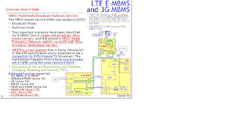
1). Modes of MBMS (Multimedia Broadcast Multicast Service)

The MBMS bearer service offers two modes in UMTS:
- Broadcast Mode;
- Multicast Mode

2). Two important scenarios have been identified for E-MBMS:

- One is single-cell broadcast (thru mixed carrier), and the second is MBMS Single Frequency Network (MBSFN via Multi-cell thru mixed or dedicated carrier).

3). Enhanced Function supported for MBMS or E-MBMS:

- GERAN/UTRAN
- UE
- BM-SC
- SGSN and GGSN
- MBMS-GW (from LTE)
- MCE (from LTE)
- E-UTRAN (from LTE)

4). MBSFN = Multimedia Broadcast multicast service Single Frequency Network

- MBSFN is a new feature that is being introduced in the LTE.

- MBSFN is envisaged for delivering services such as Mobile TV using the LTE infrastructure, and is expected to be a competitor to DVB-H-based TV broadcast.

- MBSFN Synchronization Area: NodeBs/eNodeBs can be synchronized

- MBSFN transmission or a transmission in MBSFN mode: from multiple cells within the MBSFN Area


5). MBSFN Area and Cell:

- MBSFN Area: consists of a group of cells within an MBSFN Synchronization Area of a network, which are co-ordinated to achieve a MBSFN Transmission. A cell within an MBSFN Synchronization Area may form part of multiple MBSFN Areas, each characterized by different transmitted content and participating set of cells.

- MBSFN Synchronization Area: an area of the network where all NodeBs/eNodeBs can be synchronized and perform MBSFN transmissions. MBSFN Synchronization Areas are capable of supporting one or more MBSFN Areas. On a given frequency layer, a NodeB/eNodeB can only belong to one MBSFN Synchronization Area. MBSFN Synchronization Areas are independent from the definition of MBMS Service Areas

- MBSFN Transmission or a transmission in MBSFN mode: a simulcast transmission technique realised by transmission of identical waveforms at the same time from multiple cells. An MBSFN Transmission from multiple cells within the MBSFN Area is seen as a single transmission by a UE.

- MBSFN Area Transmitting and Advertising Cell: A cell within a MBSFN Area which is contributing to the MBSFN Transmission and advertises within the cell the availability of the MBSFN Transmission.

- MBSFN Area Transmitting-Only Cell: A cell within a MBSFN Area which is contributing to the MBSFN Transmission but does not advertise within the cell the availability of the MBSFN Transmission. The need for this type of cell is FFS.

- MBSFN Area Reserved Cell: A cell within a MBSFN Area which does not contribute to the MBSFN Transmission. The cell may be allowed to transmit for other services but at restricted power on the resource allocated for the MBSFN transmission e.g. PTP for users at the centre of the cell.


6). MBSFN Overview:

- In MBSFN, the transmission happens from a time-synchronized set of eNBs using the same resource block. This enables over-the-air combining, thus improving the Signal-to-Interference plus Noise-Ratio (SINR) significantly compared to non-SFN operation.

- The Cyclic Prefix (CP) used for MBSFN is slightly longer, and this enables the UE to combine transmissions from different eNBs, thus somewhat negating some of the advantages of SFN operation.

- There will be six symbols in a slot of 0.5ms for MBSFN operation versus seven symbols in a slot of 0.5ms for non-SFN operation.

- 3GPP has defined a control plane entity, known as the MBMS Coordination Entity (MCE) that ensures that the same resource block is allocated for a given service across all the eNBs of a given MBSFN area.

- It is the task of the MCE to ensure that the RLC/MAC layers at the eNBs are appropriately configured for MBSFN operation.

- 3GPP has currently assumed that header compression for MBMS services will be performed by the E-MBMS gateway.

- Both single-cell MBMS and MBSFN will typically use point-to-multipoint mode of transmission.


7). In E-UTRAN, MBMS can be provided

Case 1). on a frequency layer dedicated to MBMS (set of cells dedicated to MBMS transmission i.e. set of "MBMS dedicated cells") and/or

Case 2). on a frequency layer shared with non-MBMS services (set of cells supporting both unicast and MBMS transmissions i.e. set of "Unicast/MBMS mixed cells").

- In both cases, single frequency network mode of operation is possible for MBMS transmission (MBSFN).


8). MCE for LTE E-MBMS

- In the 1st scenario depicted on the left MCE is deployed in a separate node.

- In the 2nd scenario on the right MCE is part of the eNBs.

- These eMBMS architecture deployment alternatives shall be applicable to both multi-cell and single cell transmission mode.


9). Multi-cell/multicast Coordination Entity (MCE) in E-MBMS

- 3GPP has defined a control plane entity, known as the MBMS Coordination Entity (MCE) that ensures that the same resource block is allocated for a given service across all the eNBs of a given MBSFN area.

- It is the task of the MCE to ensure that the RLC/MAC layers at the eNBs are appropriately configured for MBSFN operation.

- The MCE is a logical entity – this does not preclude the possibility that it may be part of another network element – whose functions are

- the allocation of the radio resources used by all eNBs in the MBSFN area for multi-cell MBMS transmissions using MBSFN operation.

- Besides allocation of the time/ frequency radio resources this also includes deciding the further details of the radio configuration e.g. the modulation and coding scheme.

- The MCE is involved in MBMS Session Control Signaling. The MCE does not perform UE - MCE signaling.


10). E-MBMS Gateway (MBMS GW) Overview

- One or more MBMS GW function entities may be used in a PLMN.

- Note that MBMS GW may be stand alone or co-located with other network elements such as BM-SC or combined S‑GW/PDN GW.

- 3GPP has currently assumed that header compression for MBMS services will be performed by the E-MBMS gateway

- The MBMS GW is a logical entity – this does not preclude the possibility that it may be part of another network element – that is present between the BMSC and eNBs whose principal functions is

- the sending/broadcasting of MBMS packets with the SYNC protocol to each eNB transmitting the service.

- The MBMS GW hosts the PDCP layer of the user plane and uses IP Multicast as the means of forwarding MBMS user data to the eNB.

- The MBMS GW performs MBMS Session Control Signalling (Session start/stop) towards the E-UTRAN.

- It provides an interface for entities using MBMS bearers through the SGi-mb (user plane) reference point;

- It provides an interface for entities using MBMS bearers through the SGmb (control plane) reference point;

- IP multicast distribution of MBMS user plane data to eNodeBs (M1 reference point);

- IP multicast distribution of MBMS user plane data to RNCs (M1 reference point);

- It allocates an IP Multicast address to which the eNodeB/RNC should join to receive the MBMS data. This IP Multicast address is provided to the eNodeB via MME and to the RNC via SGSN;

- MBMS GW supports fall back to point to point mode where applicable for UTRAN access;

- MBMS GW can communicate with multiple control plane entities (i.e. MME, SGSN and BM-SCs)


11). MBMS control & functions in E-UTRAN (eNB)

The E-UTRAN supporting MBMS comprises eNBs and co-ordinating functions.

The functions hosted by the eNB may be:

- Scheduling and transmission of MBMS control information;

- Scheduling of single-cell MBMS transmissions;

- Transmission of single-cell and multi-cell MBMS services;

- Radio bearer control for MBMS.

The co-ordinating functions may include:

- Distribution of MBMS services;

- Co-ordination of multi-cell MBMS transmissions;

- MBMS E-RAB control.


12). E-MBMS Interfaces (M1 ~ M3)

12-1). Control Plane Interfaces

“M3” Interface: MCE – MBMS GW

- An Application Part is defined for this interface between E-MBMS Gateway and MCE.

- This application part allows for MBMS Session Control Signalling on E-RAB level (i.e. does not convey radio configuration data).

- The procedures comprise e.g. MBMS Session Start and Stop.

- SCTP is used as signalling transport i.e. Point-to-Point signalling is applied.

“M2” Interface: MCE – eNB

- An Application Part is defined for this interface, which conveys at least radio configuration data for the multi-cell transmission mode eNBs and Session Control Signalling.

- SCTP is used as signalling transport i.e. Point-to-Point signalling is applied.

MBMS control plane function supporting for UTRAN:

- The MBMS control plane function is supported by MME for E-UTRAN access and by SGSN for UTRAN access.

- One or more MBMS control plane functional entities are used in a PLMN.

MME supports the following functions in order to enable MBMS support for E-UTRAN:

- Session control of MBMS bearers to the E-UTRAN access (including reliable delivery of Session Start/Session Stop to E-UTRAN);

- Transmit Session control messages towards multiple E-UTRAN nodes;

- It is FFS whether there is a need to filter the distribution of Session Control message to E-UTRAN nodes based on MBMS service area;

- It provides an Sm interface to the MBMS GW function: it receives MBMS service control messages and the IP Multicast address for MBMS data reception from MBMS GW function over the Sm interface


12-2). User Plane Interface

“M1” Interface: MBMS GW – eNB

- This interface is a pure user plane interface. Consequently no Control Plane Application Part is defined for this interface.

- IP Multicast is used for point-to-multipoint delivery of user packets for both single cell and multi-cell transmission.


13). 3GPP has defined a SYNC protocol between the E-MBMS gateway and the eNBs to ensure that the same content is sent over-the-air from all the eNBs.

- The eBM-SC is the source of the MBMS traffic

- The E-MBMS gateway is responsible for distributing the traffic to the different eNBs of the MBSFN area.

- IP multicast may be used for distributing the traffic from the E-MBMS gateway (E-MBMS GW) tothe different eNBs (eNB).

- The MBMS Synchronisation protocol (SYNC) is located in the User plane of the Radio Network layer over the Iu interface: the Iu UP protocol layer. (Iu is used between RNS --- Core Network and UTRAN --- SGSN)

- The SYNC protocol for UTRAN is used to convey user data associated to MBMS Radio Access Bearers.

- One SYNC protocol instance is associated to one MBMS RAB and one MBMS RAB only. If several MBMS RABs are established towards one given UE, then these MBMS RABs make use of several SYNC protocol instances.

- SYNC protocol instances exist at Iu access point i.e. at CN and UTRAN.

- Whenever an MBMS RAB requires transfer of user data in the Iu UP, an Iu UP protocol instance exists at each Iu interface access points. These Iu UP protocol instances are established, relocated and released together with the associated MBMS RAB.


- SYNC protocol for UTRAN. It is on top of TNL in Iu user plane, i.e. Iu userplane TNL transports SYNC protocol PDUs over the Iu interface.

- As a specification convention, within this specification, the interface between the Core Network and the Radio Access Network is denoted as the “RAN Access Interface”, the termination point at the Radio Access Network is denoted as “RAN Access Node”, the termination point at the Core Network is denoted as “Core Network” (CN). Further, “MBMS RAB” denotes the Radio Access data bearer together with the RAN Access Interface data bearer for MBMS service user data transmission.

- For the application of the SYNC protocol to UTRAN, the RAN Access Interface is the Iu interface, the RAN Access Node is the RNC.


Operation of the SYNC protocol

- The SYNC protocol layer is present for data streams that originate in the CN and carry additional information within a specific user plane-frame.

- The two strata communicate through a Service Access Point (SAP) for Non Access Stratum (NAS) Data Streams transfer.


Interfaces of the SYNC protocol layer

- As part of the Access Stratum responsibility, the SYNC protocol layer provides the services and functions that are necessary to handle non access stratum data streams for MBMS. The SYNC protocol layer is providing these services to the UP upper layers through a Dedicated Service Access Point used for Information Transfer.

- The SYNC protocol layer is using services of the Transport layers in order to transfer user plane PDUs over the RAN Access interface.


SYNC protocol layer services: The following functions are needed to support the SYNC protocol:

- Transfer of user data along with synchronisation information;

- Transfer of synchronisation information without user data.


Services Expected from the UP Data Transport layer: The SYNC protocol layer expects the following services from the Transport Network Layer:

- Transfer of user data.

- no flow control


SYNC Protocol Overview (25.446)

- SYNC Procedure - Transfer of User Data for MBMS

- SYNC Procedure - Transfer of Synchronization Information for MBMS

- SYNC Protocol - Frame format and PDU formats

- SYNC Protocol - Coding of information elements in frames


14). Two types of MBMS transmissions in E-UTRA/E-UTRAN:

a) Single-cell transmission (no MBSFN operation):

- The MBMS service, e.g. message distribution, is transmitted only on the coverage of a specific cell;

- The MBMS service (MTCH and MCCH) may be transmitted on DL-SCH (for p-t-m) or MCH (FFS);

- Combining of MBMS transmission from multiple cells is not supported;

- Scheduling is done by the eNB;

- Counting for switching between p-t-p and p-t-m radio bearer may be supported (FFS);

- The p-t-m/p-t-p switching points are either dynamically decided based on counting mechanism or semi-statically configured by O&M (FFS).

- UEs that are allocated a dedicated uplink feedback channel are in RRC_CONNECTED state.

- Multiple UEs can be allocated dedicated uplink feedback channels identical to those used in unicast transmission, which enables them to report HARQ Ack/Nack and CQI.

- To avoid unnecessary MBMS transmission on MTCH in a cell where there is no MBMS user,MCCH may announce only the availability of MBMS service(s) and the network can detect the presence in a cell of at least one MBMS user interested in the MBMS service (e.g. by polling or through UE service request) before starting the transmission on MTCH.

b) Multi-cell transmission (MBSFN operation):

- The MBMS service (MTCH and MCCH) is transmitted on MCH;

- Combining is supported with SFN - Combining of MBMS transmission from multiple cells is supported;

- Synchronous transmission of MBMS within its MBSFN Area;

- MTCH and MCCH are mapped on MCH for p-t-m transmission;

- The MBSFN Synchronization Area, the MBSFN Area, and the MBSFN Transmitting, Advertising, and Reserved cells are semi-statically configured e.g. by O&M.

- Scheduling of each MCH is done by the MCE.

- The content synchronization for multi-cell transmission is provided by some principles:

- AMC based on non-AS level feedback is FFS.


15). An E-UTRAN cell supporting MBMS is either an MBMS-dedicated cell or an MBMS/Unicast-mixed cell.

1). MBMS-dedicated cell

When a cell belongs to a frequency layer dedicated to MBMS transmission:

- MTCH and MCCH are mapped on MCH or DL-SCH (FFS) for p-t-m transmission;

- No uplink;

- No counting mechanism in another (unicast) cell supported;

- No support for unicast data transfer in the cell;

- The occurrence of paging messages on the frequency layer dedicated to MBMS transmission is (FFS):If paging messages were allowed, the UE could answer in a non-E-UTRA cell e.g. UTRA cell (FFS);


2). MBMS/Unicast-mixed cell

When a cell does not belong to a frequency layer dedicated to MBMS transmission:

- MTCH and MCCH are mapped on MCH or DL-SCH for p-t-m transmission;

- Transmission of both unicast and MBMS in the cell is done in a co-ordinated manner


16). For further information refers to

https://docs.google.com/fileview?id=F.a22ea026-06a1-4f26-8e48-911a73e911a5